Cutting Technologies
There are a couple of technologies for cutting in RDCMarkVision, help you get better processing results.
Kerf Compensation
Laser kerf is the amount of material that is removed or lost in the cutting process, and will result in dimension error if not compensated in the design.
Kerf width can vary depending on a number of factors, including the material, the thickness, the laser beam width and the power, the assist gas, etc.
Follow the steps below to find the exact kerf of a specific material cut with a specific set of parameters, e.g. 3mm acrylic cut with a 130W CO2 laser, speed set to 20mm/s and power set to 85%, etc.
- Prepare a sample of the material.
- Set the cutting parameters.
- Cut a 30mm x 30mm square.
- Measure the square with a caliper.
The half of the difference between the design and the actual size of the square is the kerf. For example, if the square measures 29.80mm, then the kerf is 0.10mm.
The kerf compensation function offsets the cutting path by exact the width of the kerf, in order to maintain the integrity of the original part size.
Select the shapes and then click ![]() on System Bar to bring up the dialog.
on System Bar to bring up the dialog.
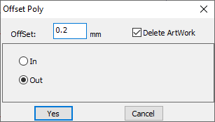
Set Offset to exact the width of the kerf, check In or Out to shrink or expand. Click Yes, the software will create new cutting paths, which are in the same distance from the originals all the way around. And the software will remove the original paths if the option Delete Artwork is checked.
Limit the Cutting Speed for Small Circles
Sometimes, you have a design with both long, smooth curves and small circles. To get good cutting quality and efficiency at the same time, you should set a high cutting speed for the whole design but limit the cutting speed for those small circles.
Click Set parameter in the pulldown-menu File or press F6 on keyboard to bring up the system parameters dialog.
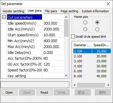
In the tab User, check the option Small circle speed limit to enable a set of cutting speed limits on small circles with different diameters. You can also add your own rules and delete the default settings.
Machine Settings for Cutting
There is a group of machine settings for cutting, which affects all jobs, saved in the laser controller. In the tab User of the system parameters dialog, click Read to read the settings from the laser.
| Parameter | Description |
|---|---|
| Idle speed | The nominal travel speed. The actual travel speed is often lower than the nominal speed due to the presence of acceleration and deceleration at the beginning and the end. |
| Idle Acc | The travel acceleration. |
| Start speed | The startup speed. |
| Min Acc | The minimum cutting acceleration. |
| Max Acc | The maximum cutting acceleration. |
| Idle Delay | The time after the laser head traveling to the start point of the cutting path and before starting cutting. |
| Acc factor | |
| G0 Acc factor | |
| Speed factor | |
| Key setting | A group of presets matching your needs. |
Before making changes, make sure to click Save to save the current settings in case of restoring after making mistakes. If you have a presets file from us, click Open to read it and update the current settings. Change the settings only if you know what you are doing. In general, you only need to choose a preset which meet your needs, and the software will adjust the settings in a whole and make a good match.
| Preset | Description |
|---|---|
| Slow cutting | The slowest mode. |
| Precision cutting | The slower mode. |
| General cutting | The medium mode. |
| Speed cutting | The faster mode. |
| Super speed cutting | The fastest mode. |
After changing the settings, make sure to click Write to update the settings in the laser.